

How To Call Out Surface Finish On A Drawing
Agreement surface roughness symbols
Symbols that indicate the surface texture of machined and structural parts are used in industrial diagrams. The pictorial representation using these symbols is defined in ISO 1302:2002.
This section volition explain how to write these symbols to indicate surface textures.
Terminology explanation
| Surface texture | This is a full general term for factors such as the roughness, necessity of removal machining, crease direction, and waviness of the surface of auto parts and structural parts. |
|---|---|
| Removal machining | This refers to the removal of surface layers from parts by mode of machining or similar methods. |
| Crease direction | This is the direction of clear creases that are formed during removal machining. |
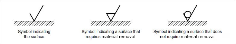
Symbols indicating target surface and the position of these symbols
When pictorially representing the surface texture, the symbol that indicates the target surface is expressed with two lines having dissimilar lengths with an bending of lx° between them.
This surface roughness indication method pictorially displays information such as the surface roughness value, cutoff value, sampling length, machining method, pucker direction symbol, and surface waviness on the surface indication symbol as shown beneath.
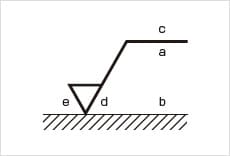
- a: Passband or sampling length and surface texture parameter symbol and value
- b: Indications of the 2d and subsequent parameters when multiple parameters are required
- c: Machining method
- d: Crease and its direction
- east: Machining assart
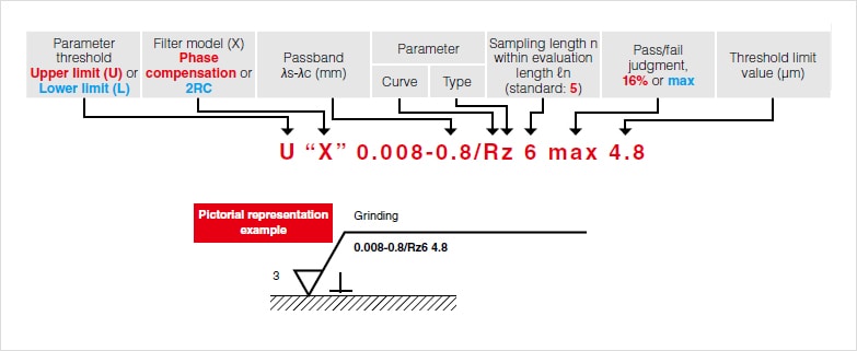
The descriptors shown below are used when pictorially representing surface roughness. However, generally speaking, the standard weather condition, which are shown in carmine, are omitted, and the indications shown in blueish are included only when necessary.
| Symbol | Meaning | Explanatory diagram |
|---|---|---|
| | The creases made by an edged tool during machining are parallel with the surface captured in the diagram in which the symbol is written. CaseShaped surface | 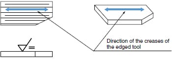 |
| | The creases made by the edged tool during machining are perpendicular to the surface captured in the diagram in which the symbol is written. ExampleShaped surface (turned on a lathe; seen from the side), cylindrically ground surface | 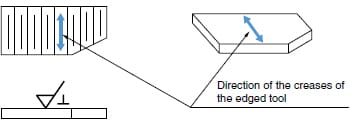 |
| | The creases made by the edged tool during machining are at an bending and cantankerous each other on the surface captured in the diagram in which the symbol is written. ExampleHoning finished surface | 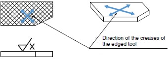 |
| | The creases made by the edged tool during machining cantankerous multiple times or have no ready management. InstanceLapped surface, super-finished surface, face-milled or end-milled surface that has been cross fed | 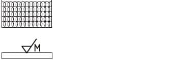 |
| | The creases made by the edged tool during machining form more often than not concentric circles in relation to the center of the surface on which the symbol is written. ExampleFaced surface | 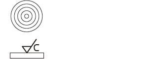 |
| | The creases fabricated by the edged tool during machining course more often than not a radial design in relation to the center of the surface on which the symbol is written. | 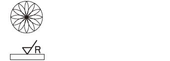 |

"What is line roughness?" page list

Source: https://www.keyence.com/ss/products/microscope/roughness/line/roughness-symbols.jsp
Posted by: williamsawfut1966.blogspot.com
0 Response to "How To Call Out Surface Finish On A Drawing"
Post a Comment